Note: Making any of these modifications risks damage to your Nex II and very likely voids your warranty! I take no responsibility for your actions.
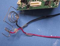
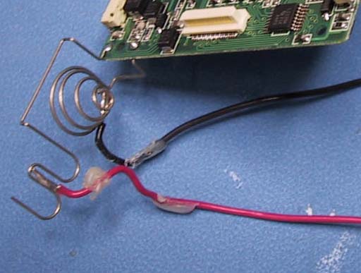
Soldering battery leads in place.
With the case off, it will be quite easy to get to the battery terminals. I managed to do it from the battery opening the first time but had to redo it later. To reduce the chance of damaging your player, use appropriately colored wires (Positive is red, Negative is black). The terminals will resist the solder a bit so you may want to use a little extra flux if available. If you have difficulty, you may consider removing the PCBs from the case entirely. (See above for tips on removing the PCBs.) Just about any soldering iron, 30W or less, should be fine for this.
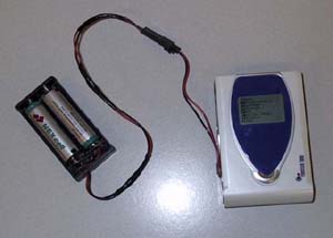
 Now you can power your Nex II using a 12V to 3V adapter in your car or even wire up a 2 D-cell battery pack for extended listening sessions. I recommend getting some sort of locking connector such as Molex or Amphenol for these. With the leads soldered in, I was still able to use internal batteries but I recommend purchasing a 2xAA battery case.
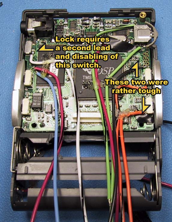
Remote Switches
This pretty much requires that you remove the bottom PCB from the case. If you are willing to make this modification then you should have little to no problems figuring out how to get the PCB from the case. Almost every hookup requires soldering onto a SM (surface mount) point.
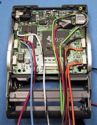 The easiest way I found to do this was use stranded wire (I used 22AWG) and clip off all but one strand. Give yourself about 3/4 of an inch and bend it so that it looks a bit like the Big Dipper. Using a 15W iron and silver bearing solder (melts at a lower temp) tin the bottom of the "ladle". This is the section you will actually attach. Press that section of wire onto your the point and then heat both of them with the iron. In a second or so, the two bits of solder will melt together. Route the wire carefully towards the bottom of the PCB. A couple of them may require using electrical tape to insulate the wire from nearby components. When all the wires are attached, I recommend securing the wires to the ICs using dabs of hot glue. Don't use too much or it may interfere with re-installation of the top PCB. Also, make sure the glue is cooled before reinstalling the upper PCB so that they don't get glued together.
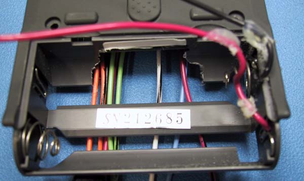
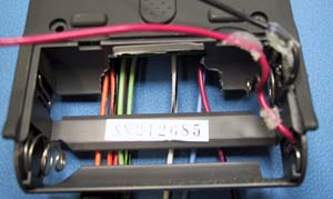 I got a little over-zealous with the Dremel here. I was hoping to just cut a slot to feed the wires through but it was too low. You should only need a small channel on either side for the wires to enter the battery section. If you aren't planning on doing the external power mod and still need to use the battery area for batteries, you may run into some difficulty feeding the wires out of the case. If you figure something out, please let me know. Either way, when the appropriate wire is shorted to ground, it triggers said function.

 I got a little over-zealous with the Dremel here. I was hoping to just cut a slot to feed the wires through but it was too low. You should only need a small channel on either side for the wires to enter the battery section. If you aren't planning on doing the external power mod and still need to use the battery area for batteries, you may run into some difficulty feeding the wires out of the case. If you figure something out, please let me know. Either way, when the appropriate wire is shorted to ground, it triggers said function.